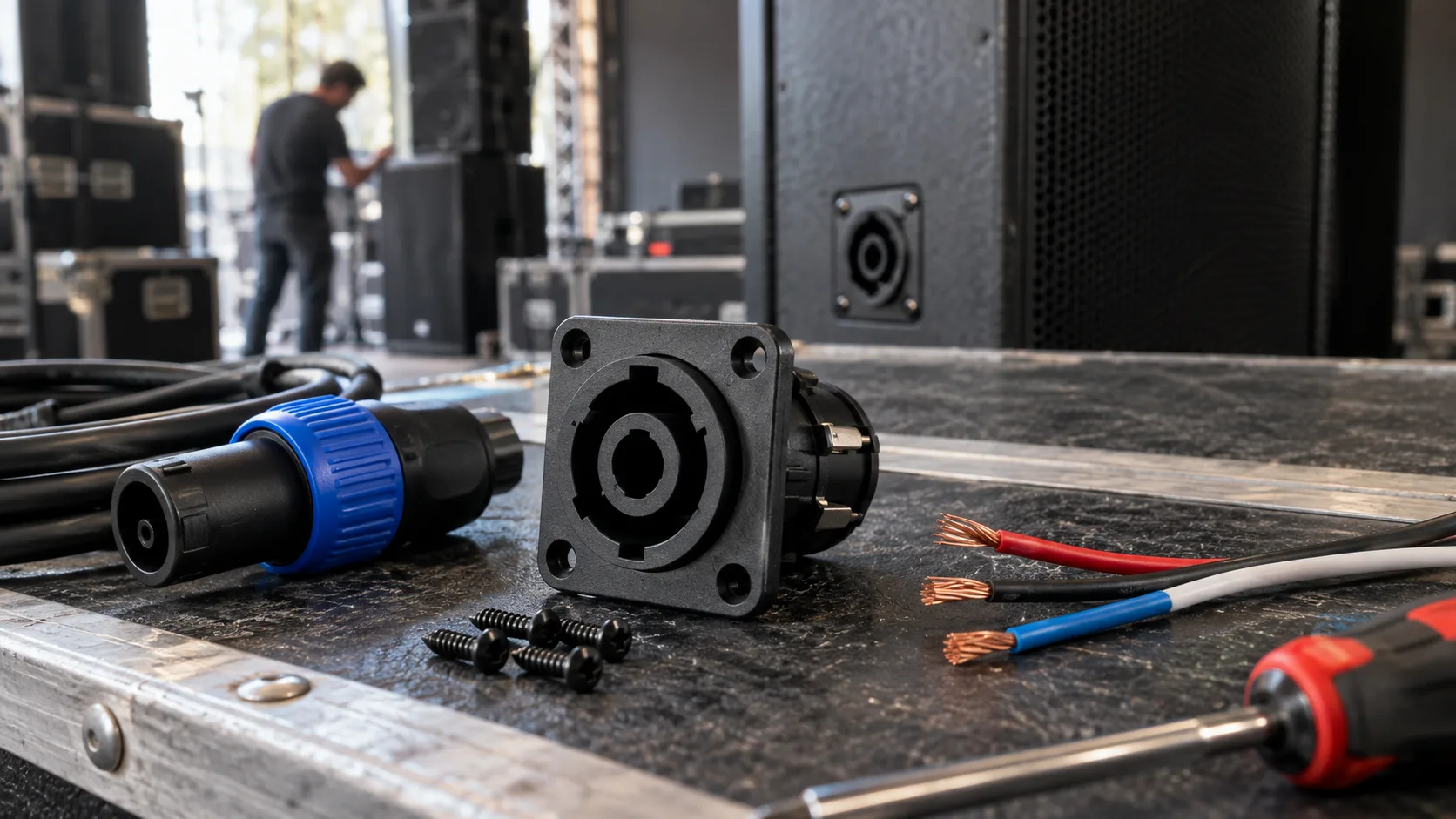
A speaker cable can pass a quick visual inspection and still be wired incorrectly. A reversed pair, one loose copper strand or a strain-relief part installed in the wrong order may not be obvious until the cable is used between a power amplifier and a loudspeaker.
Building a reliable 4 pole speaker cable connector therefore requires more than matching four conductors to four contacts. You need the pin assignment for the actual amplifier and cabinet, a cable that fits the connector, secure terminations and a complete test before the cable enters service. This guide explains that process for PA systems, stage monitors and rental cables, with the HP-07M3 as a practical NL4-compatible cable-plug example.
What the Four Contacts Actually Do
A four-pole loudspeaker interface provides two conductor pairs labeled 1+/1− and 2+/2−. Those labels identify contacts and polarity within each pair; they do not dictate one universal system function.
Many full-range passive speakers use 1+ and 1− for a single amplified circuit while leaving 2+ and 2− unused or wired through. A bi-amplified cabinet may assign one pair to the low-frequency driver and the other pair to the high-frequency driver. Some systems use the second pair to carry another amplifier channel through a four-conductor trunk cable. Neutrik’s speakON technical FAQ describes the four-pole, two-signal bi-amp application.
The equipment documentation remains the authority. Bridge-mode amplifier outputs, subwoofer pass-through arrangements and proprietary input plates may use a different mapping. Never decide the wiring from the connector shape alone.
| Contacts | Common use in a single-circuit cable | Possible use in a two-circuit cable |
|---|---|---|
| 1+ and 1− | Main speaker positive and negative | Channel A or low-frequency circuit |
| 2+ and 2− | Unused or pass-through, depending on equipment | Channel B or high-frequency circuit |
This table is a planning reference rather than a wiring instruction. Copy the exact assignment from the amplifier and loudspeaker manuals into the cable build sheet before stripping any wire.
Decide Whether You Need Two or Four Conductors
A four-pole connector does not automatically require a four-conductor cable. If the amplifier and cabinet use only 1+/1−, a two-conductor speaker cable may be appropriate. If the system carries two independent circuits, all four conductors are needed.
This distinction matters in rental and touring stock. Two cables can have identical four-pole plugs yet carry different numbers of conductors. A two-core lead placed in a bi-amp system may feed only one driver section, while a four-core lead wired for a different channel arrangement can route the wrong signal to the cabinet.
Label the finished cable with its conductor count and intended wiring. For mixed inventories, color coding or heat-shrink identification makes it easier for technicians to select the correct lead during a fast setup.
Choose Cable That Matches the System and Connector
Use cable intended for loudspeaker-level signals rather than microphone or instrument cable. Conductor size should be selected for the amplifier power, loudspeaker impedance and cable length. Longer runs and lower-impedance loads generally require heavier conductors to limit resistance and voltage drop.
The outer diameter must also fall within the connector’s supported clamping range. A cable that is too small may not be held by the strain relief; a cable that is too large may prevent the housing from closing correctly. Ask for the current HP-07M3 assembly drawing or instructions when approving a cable combination, because the public product page does not specify conductor size, strip length or cable-diameter limits.
For portable systems, also consider jacket flexibility, abrasion resistance and low-temperature handling. A stiff cable can transfer repeated bending force to the connector entry, while a soft jacket that the clamp cannot grip may pull out under load.
How to Assemble a 4 Pole Speaker Cable Connector
1. Isolate the equipment
Switch off and disconnect the amplifier before working on a speaker cable. Assemble and test the cable away from energized outputs. Loudspeaker connectors are intended for amplifier-to-speaker circuits and must not be used as AC mains or general power-supply connectors.
2. Put the housing parts on the cable first
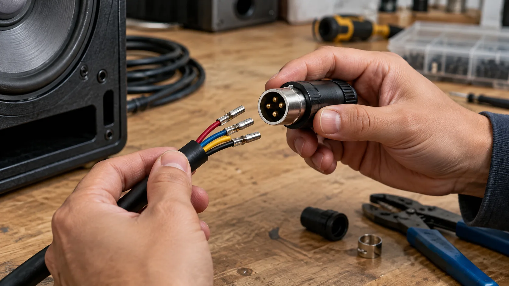
Disassemble the cable connector according to its instructions and slide the rear bushing, clamp and any other required parts onto the cable in the correct order. Forgetting this step often forces the installer to remove completed terminations and start again.
3. Prepare the jacket and conductors
Strip only the amount specified for the connector. Avoid cutting or nicking conductor strands when removing insulation. Keep the exposed copper short enough that no bare section remains outside the terminal after assembly.
For a four-conductor cable, establish a written color-to-contact map and use it at both ends. The same color must reach the same contact label from end to end. Do not rely on memory when making a batch of cables.
4. Read the molded contact labels
Locate 1+, 1−, 2+ and 2− on the connector insert. Check whether the assembly view is from the cable side or the mating side. Mirroring the contact positions is one of the easiest ways to create a cable that looks neat but fails the pin-to-pin test.
5. Terminate each conductor with no loose strands
Use the termination method and tightening requirements specified for the exact connector version. Every strand should enter the intended terminal. Loose strands can touch a neighboring contact, and excessive exposed copper can reduce separation inside the connector.
After termination, apply a light pull to each conductor before closing the housing. This catches a wire that appears seated but is not securely retained.
6. Engage the strain relief on the cable jacket
The clamp should grip the outer jacket, not the insulated inner conductors. Its job is to keep pulling and bending loads away from the electrical terminations. Align the clamp and housing features correctly, then close the connector without pinching or twisting the conductors.
7. Repeat the same verified map at the other end
Build the second end from the same wiring sheet. If the cable intentionally changes contact pairs for a special system, mark both ends clearly and keep it separate from ordinary straight-through leads.
Test the Cable Before Connecting a Loudspeaker
A multimeter test should be part of every new build and repair. Keep the cable disconnected from all equipment while checking it.
- Verify continuity from 1+ at one end to the intended contact at the other end.
- Repeat for 1−, 2+ and 2− as applicable.
- Confirm that no contact is shorted to another contact.
- Flex the cable near both connector entries while watching the meter for intermittent changes.
- Check that both connectors lock and release correctly with the intended mating sockets.
For production batches, record the test result against the cable or lot number. A simple pin-to-pin fixture can make repetitive inspection faster and reduce the risk of overlooking one pair.
After the electrical test passes, connect the cable to the intended system with amplifier level reduced. Verify that the correct cabinet sections operate and listen for intermittent output while the cable remains stationary. Do not troubleshoot a suspected wiring fault by repeatedly plugging and unplugging an active high-level output.
Common Assembly Mistakes and Their Symptoms
| Mistake | Likely result | Corrective check |
|---|---|---|
| Mating-side and cable-side views are confused | Contacts are mirrored | Read the molded labels and test every contact end to end |
| 1+/1− and 2+/2− are assigned from memory | Wrong driver section or no output | Use the amplifier and cabinet pinout |
| Loose strands remain outside a terminal | Intermittent signal or a short | Re-strip and re-terminate the conductor |
| Clamp grips inner conductors | Terminations carry mechanical load | Reassemble the strain relief on the outer jacket |
| Two-core cable is used for a two-circuit system | One circuit is absent | Confirm conductor count before assembly |
| Cable is accepted without a flex test | Fault appears only during handling | Monitor continuity while bending each cable entry |
Where the HP-07M3 Fits
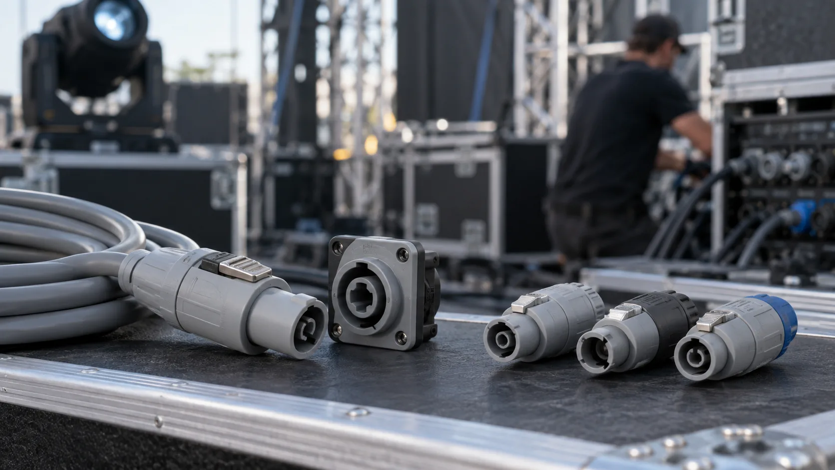
The HP-07M3 4 Pin Speakon Connector Speaker Cable Plug is a female cable-mount connector for professional loudspeaker wiring. The product page identifies an NL4-compatible interface, a twist-lock mechanism and a durable nylon housing. It lists an insertion force of no more than 20 N and a service life above 1,000 mating cycles.
Those characteristics make the model relevant to PA leads, stage-monitor cables, amplifier-to-speaker connections and rental inventory where cables are connected repeatedly. The twist-lock format helps resist accidental disconnection, but cable reliability still depends on correct termination, strain relief and inspection.
Before approving the HP-07M3 for a project, request the current drawing and assembly requirements. Test a sample with the chosen cable and the actual chassis socket. For a wider comparison, review the SpeakON connector range, which includes cable and panel components for different audio assemblies.
Match the Cable Plug to the Panel Socket
Interface compatibility is only one part of the connection. The amplifier or loudspeaker socket must use the same contact assignment, and its electrical and mechanical specifications must suit the system.
If you are designing or replacing the chassis side, the separate 4 pin panel mount socket wiring guide covers cutouts, rear clearance and internal cabinet wiring. Treat the cable assembly and panel assembly as one signal path, then test the complete path before the equipment enters service.
What Buyers Should Confirm Before a Bulk Order
For an OEM cable assembly or distributor order, send more than a connector model number. Provide the cable type, outer diameter, conductor count and size, required length, pin map, mating socket and expected operating environment. Include labeling, color coding and packaging requirements if the cables will join an existing inventory.
Ask the supplier for the current drawing, termination instructions and relevant ratings for the exact model. Approve a fully assembled sample before committing to volume. Inspect the sample for terminal retention, jacket clamping, connector locking and pin-to-pin continuity.
A clear build specification also prevents an unintentional change between batches. Keep the approved sample and wiring sheet as the reference for incoming inspection.
Frequently Asked Questions
What is the standard pinout for a 4 pole speaker cable?
The contacts are labeled 1+, 1−, 2+ and 2−, but their system functions depend on the amplifier and loudspeaker. Many single-circuit systems use 1+/1−; bi-amp and multi-channel systems may use both pairs. Follow the equipment manuals.
Can I use a two-conductor cable with a four-pole plug?
Yes, when the equipment needs only one pair and the cable meets the system requirements. It will not carry a second circuit, so label it clearly and do not use it where four conductors are required.
How do I know whether 2+/2− are used?
Check the amplifier output diagram and the loudspeaker input-plate documentation. A continuity test can show how an unpowered cable is wired, but it does not define what the equipment expects.
Why does a newly assembled speaker cable cut out when moved?
A poorly retained conductor, damaged strand or ineffective strain relief is a common cause. Disconnect the cable, open both ends, inspect the terminations and repeat the continuity test while flexing the entries.
Is the HP-07M3 suitable for every NL4-style system?
Its product page states NL4 interface compatibility, but the cable, termination requirements, electrical ratings and system pinout must still be checked for the application. A sample test with the intended socket is the safest approval method.
Build the Cable Around a Documented Pin Map
A dependable four-pole speaker lead starts with a verified wiring diagram and ends with a complete electrical and mechanical test. Select the conductor count for the actual system, keep the contact labels consistent, clamp the outer jacket and test every connection before applying an amplified signal.
For PA cable manufacturing, replacement leads or OEM audio projects, the HP-07M3 provides a four-pole, twist-lock cable-connector option to evaluate. Compare it with the intended cable and chassis socket, approve a sample, and keep the final pin map with the assembly specification.