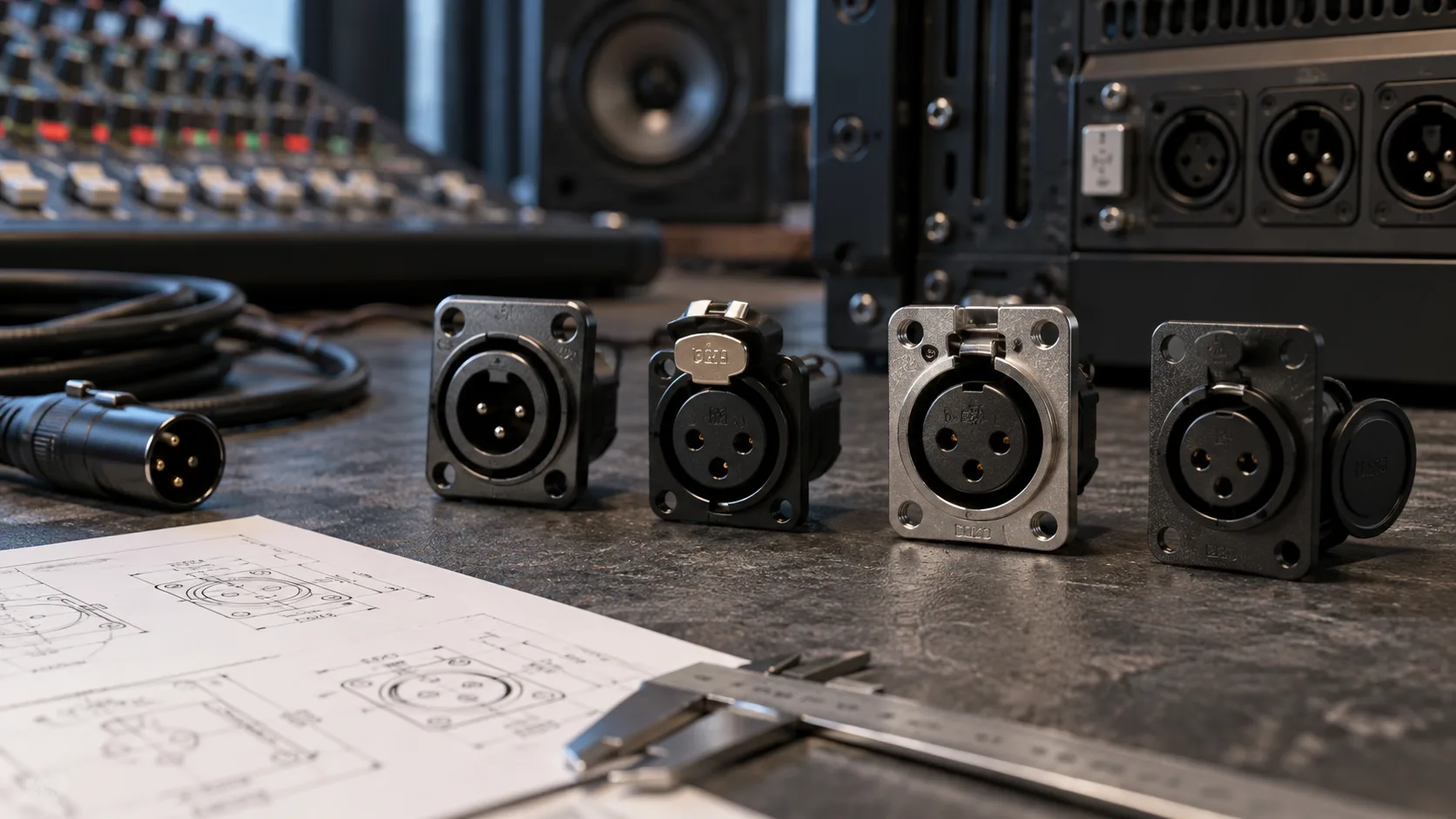
An audio input that accepts both an XLR plug and a quarter-inch jack can make a compact mixer or interface easier to use. For equipment designers, it also reduces the number of separate connector positions needed on the front panel. But choosing an XLR combo jack requires more than matching its visible shape.
The connector must fit the enclosure, match the circuit board or wiring arrangement, and provide the contacts needed by the input design. This guide explains how an XLR and 1/4-inch combo socket works, what to check before selecting one, and where the CTCK-12WP-07 fits into a professional audio project.
What Is an XLR and 1/4-Inch Combo Jack?
An XLR combo jack combines an XLR receptacle and a 6.35mm phone jack in a shared housing. A user can insert an appropriate XLR plug or a quarter-inch jack plug into the same panel position. The formats are alternatives: one combo socket does not accept both plugs at the same time.
This arrangement is useful when a channel needs to accommodate different source connections without allocating separate front-panel sockets to each format. Neutrik’s combo connector FAQ describes this combined construction and notes that switching-contact variants are available. The precise contact arrangement still depends on the selected model.
One socket also does not automatically mean two independent audio channels. The equipment’s circuitry determines how the contacts are routed and what signal types the input can handle.
Mic, Line and Instrument Inputs: The Circuit Makes the Difference
Microphones, line-level sources and passive instruments have different input requirements. The fact that a plug fits a socket does not prove that the input provides the appropriate gain, impedance or headroom.
| Source | Common connection on audio equipment | What the input design must provide |
|---|---|---|
| Microphone | XLR | A suitable microphone input stage and gain range |
| Line-level source | 6.35mm TRS or TS, depending on the equipment | Line-level handling and appropriate headroom |
| Passive guitar or bass | 6.35mm TS | A suitable high-impedance instrument input |
For example, Focusrite’s 18i8 hardware guide distinguishes combo inputs that accept instrument signals from other combo inputs intended for microphone or line signals. Similar-looking sockets can therefore serve different functions within the same device.
For an OEM design, decide which source types each channel should support before choosing the connector and its contact configuration. For a repair, preserve the original circuit’s input behavior rather than assuming that a new combo socket adds capabilities.
Where the CTCK-12WP-07 Fits
For equipment requiring both plug formats in one panel position, the CTCK-12WP-07 XLR Female Combo Jack Panel Socket is a model to evaluate. Chengyu Tech describes it as a female XLR and 1/4-inch combination connector for panel-mounted audio inputs.
The product page lists mixers, audio interfaces, stage boxes, amplifiers and rack-mounted equipment among its applications. Its shared interface is relevant when several channels, controls and indicators must fit into a limited panel area. OEM/ODM support is also listed for projects requiring customization.
Before approving it for a build, request the exact mechanical drawing and contact diagram. The product’s application description does not establish a particular PCB footprint, switching function or high-impedance input circuit.
XLR Combo Socket vs Separate XLR and Jack Inputs
A combo socket is useful when the user needs a choice of plug format for one input position. Separate sockets can be useful when a design needs more physical separation or different connector placement. Neither arrangement determines the number of usable channels by itself.
| Design question | Combo socket | Separate sockets |
|---|---|---|
| Panel layout | Combines two plug formats in one location | Allocates separate locations to the formats |
| User labeling | Needs clear labels for supported input modes | Allows labels beside each socket |
| Internal design | Requires a suitable contact arrangement and routing | Requires routing between separate components |
| Service replacement | Must match the combined footprint and contacts | Each connector can be evaluated separately |
Choose the layout around how the channel will be used. If one source is connected at a time and front-panel space is limited, a combo socket is worth considering early in the mechanical design.
Five Checks Before Selecting a Panel Mount Combo Jack
1. Panel opening and plug clearance
Compare the specified cutout and mounting positions with the enclosure drawing. Include the space needed to insert and remove both plug types. Nearby gain controls or a recessed panel can make a socket awkward to use even when its body fits the opening.
2. Rear clearance and terminal arrangement
Check the space behind the panel with the connector installed. Confirm the termination style, terminal dimensions and any PCB footprint against the supplier’s drawing. The words “panel mount” do not specify how the electrical connections are made.
3. Jack contacts and switching behavior
Request a contact diagram showing the jack connections and any contacts that change state when a plug is inserted. If the circuit uses insertion detection or switched routing, the replacement must provide the required behavior. Do not assume every combo socket includes the same switch contacts.
4. Mechanical support
Evaluate how insertion and removal forces are supported by the enclosure and mounting hardware. A connector should be installed according to its intended mounting arrangement, with adequate support for the finished assembly. Review this with the panel and PCB together rather than as separate parts.
5. Documented operating conditions
The CTCK-12WP-07 page lists a temperature range of −20°C to +65°C and a life figure of 5,000 operations. Ask the supplier for the corresponding test conditions when using these values in a purchasing specification. Confirm electrical and mechanical requirements for the exact component revision.
Does a TRS Jack Mean Stereo?
TRS describes three plug contacts: tip, ring and sleeve. The signal assignment depends on the equipment. In an audio input, those contacts may carry a balanced mono signal; in another application, they may carry left and right audio plus a common connection.
Consequently, a combo socket should not be labeled “stereo input” solely because its jack section has three contacts. Specify the intended signal assignment in the schematic and user documentation, then confirm that the selected connector provides the required contacts.
Test a Sample Before a Production Order
Fit a sample in a representative enclosure and evaluate both plug formats separately. Check insertion, removal, alignment and clearance around adjacent controls. With the assembly unpowered, verify the contact mapping and any switching states against the approved schematic.
Then test the completed input circuit with the source types it is intended to accept. A microphone test alone does not validate the jack input, and a line-level test does not establish instrument-input performance.
For a project considering this part, send the supplier your panel drawing, termination requirements, contact configuration and estimated quantity with the CTCK-12WP-07 product reference. This helps establish whether the standard part fits your design before committing to tooling or bulk purchasing.
Frequently Asked Questions
Can I connect an XLR microphone and a jack cable at the same time?
Not through the same combo socket. The shared opening accepts one plug format at a time.
Will a combo jack automatically accept a passive guitar?
The device needs an appropriate instrument input stage. The connector alone does not provide the required input impedance or gain behavior.
Can the CTCK-12WP-07 replace any XLR combo socket?
Check the panel opening, mounting arrangement, termination details and contact diagram first. A similar front appearance does not establish a compatible replacement.
Does a combo socket provide phantom power?
No. Phantom power is supplied and controlled by the equipment’s circuitry. Its implementation must follow the circuit design and the component specifications.
What should I request before ordering in bulk?
Request the current drawing, contact diagram, termination details, test conditions and samples. Evaluate them against your enclosure and input circuit before approving the part for production.